Need Help with DualOptiboot Fota
-
Hi everyone,
I just discovered MyController, following the use of MySensors 2.3.2 and I see that there is a lot of potential compared to MYScontroller: bravo to the whole team!What works: My Nodes and Gateway (serial) work and are recognized in MYController.
The (minimum) equipment to test FOTA: I have a 328p Bare Bone (8MHz internal) + SPI Flash memory + 3.3v regulator + RFM69HCW.
What I would like to do: if I understood correctly: just burn the DualOptiboot bootloader WITHOUT SKETCH. The first time it is turned on, it will ask MYController for an identifier and I could load the sketch from MYController OTA:Actions >> Upload firmware.It's just ?
For that, I need the
DualOptiboot.hexwhich corresponds to my Node (8MHz internal, BOD 2.7v ...) which I must flash in my 328P with AVRDUDESS.Someone to help me find this bootloader.
-
@superninja Welcome to MyController
")
I usually go with Sensebender bootloader.
Steps :- setup Arduino IDE for Sensebender - https://github.com/mysensors/ArduinoBoards
- Select your hardware details. from your input, the board: sensbender, 328 + 8 Mhz
- Burn bootloader from IDE (it should be DualOptiboot)
- add a sketch with
#define MY_OTA_FIRMWARE_FEATURE- https://github.com/mysensors/MySensors/blob/2.3.2/MyConfig.h#L1222~L1253
Afterburn DualOptiboot, you should add a MySensors sketch via serial (OTA feature should be enabled on your sketch). From this point, OTA works with DualOptiboot
-
@jkandasa Thanks for this fast and clear response , i'll test this and come back here .
-
@jkandasa this is what i do :
-
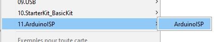
I loaded the
ArduinoISPsketch on an Arduino PRO mini to use as a programmer.
-
then I configured Arduino IDE with the SensBender 8MHz board like this:
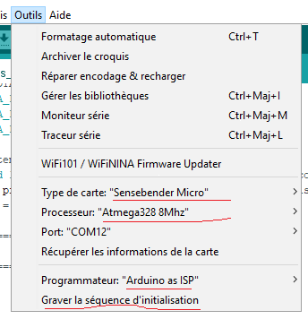
and I started the bootloader burning which went well. -
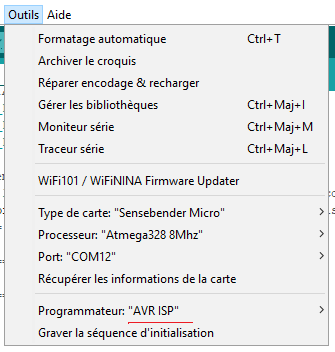
I unplugged the ProMini and plugged in an FTDI converter to program the ATMega 328P by configuring like this:
I injected this simple BLINK LED sketch :
// Enable debug prints to serial monitor //#define MY_DEBUG //debug de MySensors //#define MY_DEBUG_VERBOSE_SIGNING //debug de la signature //===== RFM config ===== #define MY_RADIO_RFM69 #define MY_IS_RFM69HW //with H(CW) #define MY_RFM69_NEW_DRIVER #define MY_RFM69_FREQUENCY RFM69_868MHZ #define MY_SIGNAL_REPORT_ENABLED //#define MY_RFM69_ATC_TARGET_RSSI_DBM (-80) //#define MY_RFM69_MAX_POWER_LEVEL_DBM (10) // max. TX power 10dBm = 10mW //1mW = 0dBm 10mW = 10dBm 25mW = 14dBm 100mW = 20dBm //#define MY_DEBUG_VERBOSE_RFM69 //debug du signal RF //#define MY_RFM69_NETWORKID 101 #define MY_RFM69_IRQ_PIN 2 #define MY_RFM69_CS_PIN 10 //===== LED ===== #define LED_BUILTIN 9 //pb1 pin15 //========== NODE ID ========== #define MY_NODE_ID 4 //#define MY_NODE_TYPE "NODE" //#define CHILD_ID 1 // Id of the sensor child #include <SPI.h> #include <MySensors.h> #include <Wire.h> //pr1:===== FOTA ===== #define MY_OTA_FIRMWARE_FEATURE #define MY_OTA_FLASH_SS (8) #define MY_OTA_FLASH_JDECID (0xBF26) //Use (0x00) if unknown. //pr2: ===== tempo non bloquante ===== const unsigned long BLINK_INTERVAL = 1000;// Nombre de millisecondes entre deux changements d'état de la LED unsigned long previousMillis = 0;// Précédente valeur de millis() byte ledState = LOW;// Précédent état de la LED //=================================== //= BEFORE = //=================================== void before() { } //FIN de before //=================================== //= SETUP = //=================================== void setup() {//pas besoin de Serial.begin(115200) pinMode(LED_BUILTIN, OUTPUT);// Configure la broche de la LED en sortie digitalWrite(LED_BUILTIN, ledState); // Configure l'état initial de la LED }//FIN du SETUP //========================================== //= PRESENTATION = //========================================== void presentation() { // Send the sketch version information to the gateway and controller sendSketchInfo("led fota", "1.0"); } // FIN de PRESENTATION //=================================== //= LOOP = //=================================== void loop() { unsigned long currentMillis = millis(); // Récupére la valeur actuelle de millis() if (currentMillis - previousMillis >= BLINK_INTERVAL) // Si BLINK_INTERVAL ou plus millisecondes se sont écoulés { previousMillis = currentMillis; // Garde en mémoire la valeur actuelle de millis() ledState = !ledState; // Inverse l'état de la LED digitalWrite(LED_BUILTIN, ledState); Serial.print("LED "); Serial.println(ledState); } }// FIN de LOOP-
the led is flashing well and MYController sees the node

-
I change the flashing delay from 1000 to 500 and the version which goes from 1.0 to 1.1. I compile the sketch which gives me:
moteino_MySensors_fota_pr1.ino.hex -
I go to
Utilities>>Firmwareand add a Type, Version 1.1 and Firmware (with faster flashing delay)

-
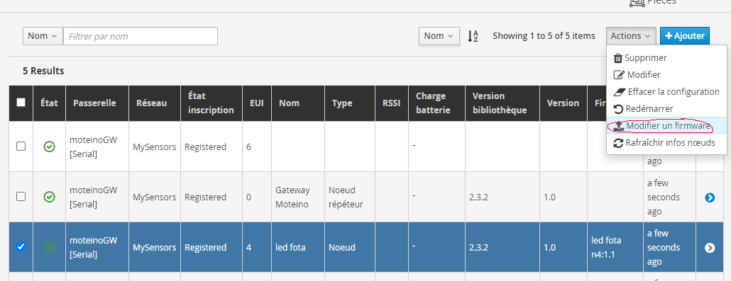
I go back to
Resources>>nodesand upload the firmware of this node n°4
-
and ...nothing after 7 minutes

Any Idea ? My Sketch is wrong ?
-
-
@superninja you can see some staus on the node page. also on the
Status >> Resource logs, you can see some messages. EnableSettings >> System >> MyController >> Resources logs levelto notice or debug.also try
#define MY_OTA_FLASH_JDECID 0x00, which works for me. -
@jkandasa Thank you for your help: I summarize what you asked me to do and which works now:
The (minimum) equipment to test FOTA: I have a ATMega 328p BareBones (8MHz internal) + led attached to PB1 (pin15)+ SPI Flash memory + 3.3v regulator + RFM69HCW.- Install ArduinoISP program to ProMini (Programmer)
- Connect MySensors board on ProMini (ArduinoISP) via ISP header
- Select, Programmer="Arduino as ISP", Board:"Sensbender Micro", Processor:"Atmega 328 8Mhz"
- Now click on "Burn Bootloader". bootloader will be loaded on MySensors board
- Remove ISP header and remove ProMini from your computer
- Connect MySensors board to USB via FTDI connector
- Upload MySensors sketch(OTA should be enabled on the sketch) to MySensors board
- Now the MySensors node will appear in MyController server.
- Modify the MySensors sketch and upload it to MyController
- Now trigger "Firmware upload" from MyController server page.
This is the first sketch to upload one time with the USB to FTDI connector :
//pr1: minimal sketch for fota with blink led


#define blinkTime 200
#define SKETCH_NAME "SensBender Led 200 -70"  //25 caracteres max
#define SKETCH_VERSION "pr1"

//===== RFM config =====
// Enable and select radio type attached
#define   MY_RADIO_RFM69
//#define   MY_DEBUG_VERBOSE_RFM69
//#define   MY_DEBUG_VERBOSE_RFM69_REGISTERS

#define   MY_RFM69_NEW_DRIVER
//#define MY_RFM69_ATC_MODE_DISABLED
#define MY_RFM69_ATC_TARGET_RSSI_DBM (-70)  // target RSSI -70dBm//BUG
//#define MY_RFM69_MAX_POWER_LEVEL_DBM (20)   // max. TX power 10dBm = 10mW//MARCHE
#define   MY_RFM69_FREQUENCY (RFM69_868MHZ)
#define   MY_IS_RFM69HW //with H(CW)
//#define   MY_RFM69HW (true)
//#define   MY_RFM69_NETWORKID (100)

//#define MY_RFM69_BITRATE_MSB (RFM69_BITRATEMSB_1200)
//#define MY_RFM69_BITRATE_LSB (RFM69_BITRATELSB_1200)

// Enable repeater functionality for this node
//#define MY_REPEATER_FEATURE

#define MY_DEBUG

//===== LED =====
#define LED_BUILTIN 9       //pb1 pin15

//===== This Node ID =====
#define MY_NODE_ID 0x02

//===== Enable OTA feature =====
#define MY_OTA_FIRMWARE_FEATURE
#define MY_OTA_FLASH_SS (8)       //pb0 pin14
#define MY_OTA_FLASH_JDECID 0x00  //0x00 if you don't know

#include <MySensors.h>

//===================================
//=              SETUP              =
//===================================
void setup() {//pas besoin de Serial.begin(115200)
  pinMode(LED_BUILTIN, OUTPUT);
  Serial.print("Start "); Serial.print(SKETCH_NAME); Serial.print(" "); Serial.println(SKETCH_VERSION);
}//FIN du SETUP
//==========================================
//=              PRESENTATION              =
//==========================================
void presentation() {
  // Send the sketch version information to the gateway and controller
  sendSketchInfo(SKETCH_NAME, SKETCH_VERSION);
} // FIN de PRESENTATION
//===================================
//=              LOOP               =
//===================================
void loop() {
  digitalWrite(LED_BUILTIN, HIGH);  Serial.print("LED ON ");
  wait(blinkTime);
  digitalWrite(LED_BUILTIN, LOW);  Serial.println("LED OFF ");
  wait(blinkTime);
}// FIN de LOOP
Change
blinkTimetime and compil the sketch , then upload firmware.hexwith MYCONTROLLER.
Enjoy