@jkandasa Thank you for your help: I summarize what you asked me to do and which works now:
The (minimum) equipment to test FOTA: I have a ATMega 328p BareBones (8MHz internal) + led attached to PB1 (pin15)+ SPI Flash memory + 3.3v regulator + RFM69HCW.
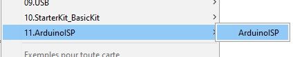
- Install ArduinoISP program to ProMini (Programmer)
- Connect MySensors board on ProMini (ArduinoISP) via ISP header
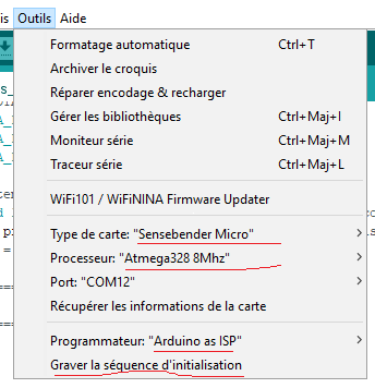
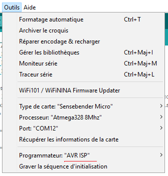
- Select, Programmer="Arduino as ISP", Board:"Sensbender Micro", Processor:"Atmega 328 8Mhz"
- Now click on "Burn Bootloader". bootloader will be loaded on MySensors board
- Remove ISP header and remove ProMini from your computer
- Connect MySensors board to USB via FTDI connector
- Upload MySensors sketch(OTA should be enabled on the sketch) to MySensors board
- Now the MySensors node will appear in MyController server.
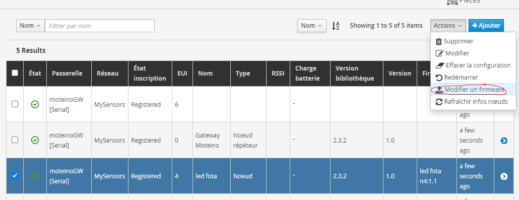
- Modify the MySensors sketch and upload it to MyController
- Now trigger "Firmware upload" from MyController server page.
This is the first sketch to upload one time with the USB to FTDI connector :
//pr1: minimal sketch for fota with blink led


#define blinkTime 200
#define SKETCH_NAME "SensBender Led 200 -70"  //25 caracteres max
#define SKETCH_VERSION "pr1"

//===== RFM config =====
// Enable and select radio type attached
#define   MY_RADIO_RFM69
//#define   MY_DEBUG_VERBOSE_RFM69
//#define   MY_DEBUG_VERBOSE_RFM69_REGISTERS

#define   MY_RFM69_NEW_DRIVER
//#define MY_RFM69_ATC_MODE_DISABLED
#define MY_RFM69_ATC_TARGET_RSSI_DBM (-70)  // target RSSI -70dBm//BUG
//#define MY_RFM69_MAX_POWER_LEVEL_DBM (20)   // max. TX power 10dBm = 10mW//MARCHE
#define   MY_RFM69_FREQUENCY (RFM69_868MHZ)
#define   MY_IS_RFM69HW //with H(CW)
//#define   MY_RFM69HW (true)
//#define   MY_RFM69_NETWORKID (100)

//#define MY_RFM69_BITRATE_MSB (RFM69_BITRATEMSB_1200)
//#define MY_RFM69_BITRATE_LSB (RFM69_BITRATELSB_1200)

// Enable repeater functionality for this node
//#define MY_REPEATER_FEATURE

#define MY_DEBUG

//===== LED =====
#define LED_BUILTIN 9       //pb1 pin15

//===== This Node ID =====
#define MY_NODE_ID 0x02

//===== Enable OTA feature =====
#define MY_OTA_FIRMWARE_FEATURE
#define MY_OTA_FLASH_SS (8)       //pb0 pin14
#define MY_OTA_FLASH_JDECID 0x00  //0x00 if you don't know

#include <MySensors.h>

//===================================
//=              SETUP              =
//===================================
void setup() {//pas besoin de Serial.begin(115200)
  pinMode(LED_BUILTIN, OUTPUT);
  Serial.print("Start "); Serial.print(SKETCH_NAME); Serial.print(" "); Serial.println(SKETCH_VERSION);
}//FIN du SETUP
//==========================================
//=              PRESENTATION              =
//==========================================
void presentation() {
  // Send the sketch version information to the gateway and controller
  sendSketchInfo(SKETCH_NAME, SKETCH_VERSION);
} // FIN de PRESENTATION
//===================================
//=              LOOP               =
//===================================
void loop() {
  digitalWrite(LED_BUILTIN, HIGH);  Serial.print("LED ON ");
  wait(blinkTime);
  digitalWrite(LED_BUILTIN, LOW);  Serial.println("LED OFF ");
  wait(blinkTime);
}// FIN de LOOP
Change blinkTime time and compil the sketch , then upload firmware .hex with MYCONTROLLER.
Enjoy